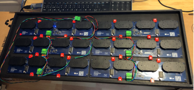
Have any last-minute projects you finished just before the end of the decade? To help pass the time, [Erich Styger] decided to build a meta digital clock made up of 24 individual analog clocks, the perfect item to help welcome in the new year. The stepper clock is controlled by a network of LPC microcontrollers, displaying the time and room temperature, as well as several aesthetically pleasing loading animations.
Each clock operates from a 5 V USB power bank drawing less than 2 A for the full 24-clock setup. The meta-clock resides in a laser cut enclosure, with 3D printed hands telling the time. While having one board per clock would be easier to implement, [Erich] decided to use one board per four clocks arranged in rows to save on costs. The arrangement fixes the distance between clocks, though [Erich] also made the clock size slightly smaller to compensate.

The 'stepper' part of the stepper clock uses a 360 degree version of the VID28 stepper motor to reduce the height of the design and the cost of the project. Apart from the X12.017 driver silently driving the motors, the stepper motors also conveniently only need a 'direction' and 'step' pin, reducing the pin count needed for the microcontroller. Neodymium magnets and hall effect sensors are used for tracking the position of the hands as the clocks move, with the magnets embedded into the clock hands.
As for communication, rather than use the common I2C protocol, the more robust RS-485 was selected. A master coordinates all of the clocks using the bus, providing a command line interface. The master is also able to communicate with the host PC over USB to maintain RTC time.
During the software development phase, [Erich] made use of the SEGGER J-Link EDU mini CLI for keeping track of information about the driver and each individual stepper motor. The software controlling the motors is written in C, with boards running FreeRTOS. The stepping is handled with a timer interrupt, but because the LPC845 doesn't have enough timer channels, all of the functionality is done within a single channel. This results in plenty of interrupt handlers, flags, and callbacks across the code, which makes for some good fun.
Speaking of clocks, check out some of our other past clock hacks, including this mini-VFD clock and this fun LED matrix clock (it lets you play Tetris!)
via https://ift.tt/2SL5z8n

No comments:
Post a Comment